DIY自动售货机——基于Arduino的机电一体化项目
在这个项目中,我们将学习如何制作基于Arduino的DIY自动售货机。我将向您展示构建它的整个过程,从切割和组装MDF板到将所有电子部件连接在一起并编写Arduino代码。
概述
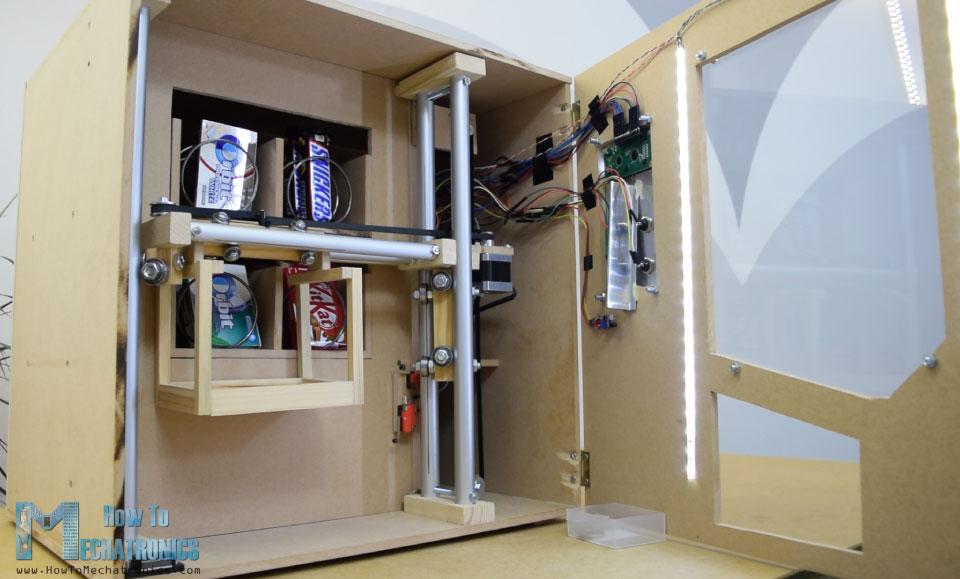
自动售货机具有四个连续旋转伺服电机控制的四个出料单元、步进电机控制的载体系统、液晶显示器、四个选择物品的按钮和硬币检测器。
你现在可能会想,这个自动售货机没有那么有用,是的,你可能是对的。但我的想法是让这个项目更有趣或者更复杂,这样你就能学到更多新东西。我认为这个项目的想法可以很好的为电子或机电一体化的学生考虑建设一个作为他们的最后一年的项目,以及任何阿杜诺爱好者。
建造自动售货机
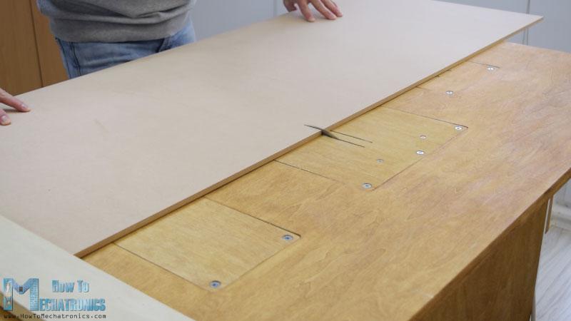
我从切割8毫米厚的中密度纤维板开始。
我以前做了一个三维模型的机器,从那里我得到了所有的测量。您可以从下面的链接下载三维模型。
我用圆锯切割中密度纤维板。实际上这是一个,由我的搭档Marija制作,在她的YouTube频道上有一段DIY视频 .
在用圆锯切割了所有的面板之后,我继续用倒置的拼图在一些面板上开孔。
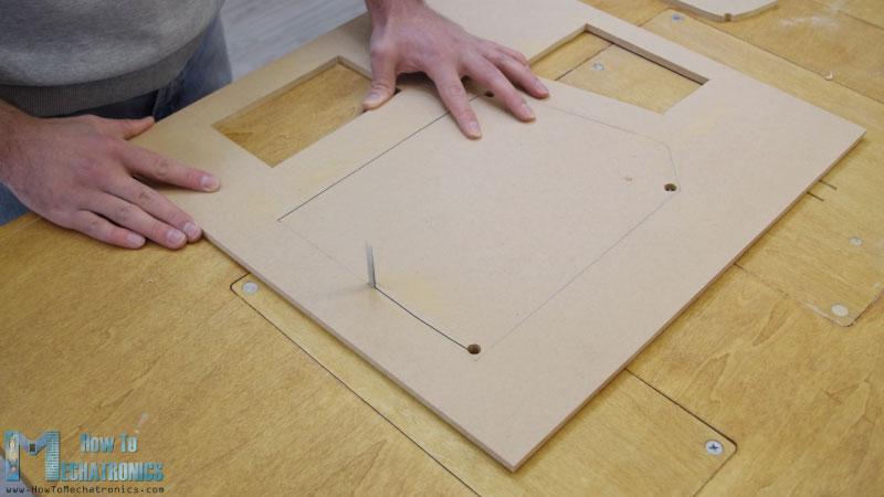
实际上,一个拼图甚至可以用于前一步,以防你没有圆锯。我也用拼图切割有好几个切口的小零件。但是,请注意,这些是危险的机器,所以在使用它们时需要非常小心。
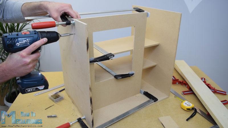
当我准备好所有的MDF部件后,我开始用一些木胶和螺丝组装它们。为了紧固面板,我用了90度角夹钳。使用无绳钻,我首先做了试点孔,然后做了柜台下沉和螺丝3毫米的螺丝到位。我用同样的方法组装了所有的面板,其中一些面板我还使用了一些F夹具。
轨道系统
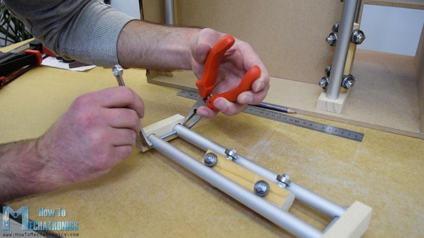
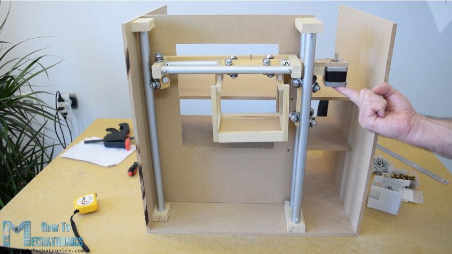
在装配的这一点上,我将继续制作轨道系统。为此,我使用铝管,我用金属手锯将它们切割成一定的尺寸。水平轨道的管道直径为16 mm,而垂直轨道的管道直径为20 mm。在一个18毫米的实木板上,我用福斯特纳钻头为管子做了槽,然后把管子连在上面。
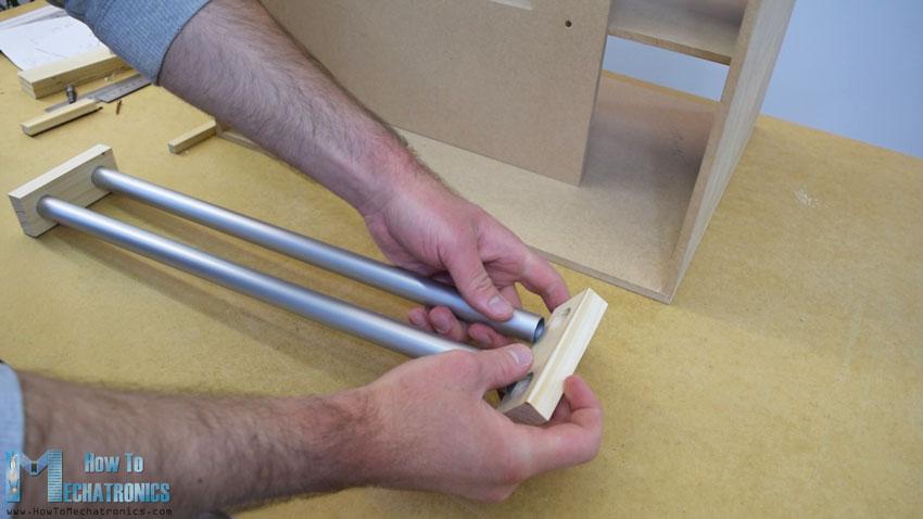
水平轨道由两根27厘米长的管子组成,而垂直轨道由三根45厘米长的管子组成。
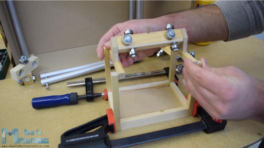
接下来是滑块,下面是我如何制作的。我用21×21厘米的木板在上面打了8毫米的洞。
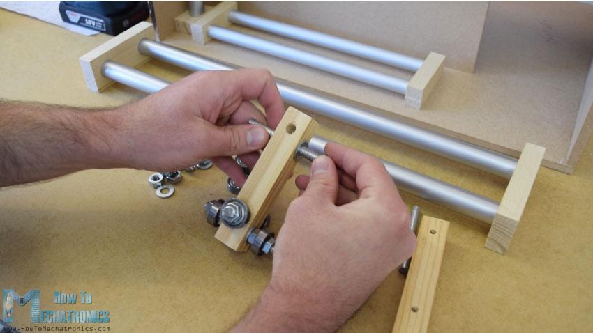
然后我通过这些孔插入8毫米螺纹杆,并用垫圈和螺母固定22毫米轴承。至于水平滑块,我使用了相同的方法,但直径较小的轴承为16毫米。
当我把滑块插入管轨之间时,我发现它有点松。为了解决这个问题,我不得不缩短两条铁轨之间的距离。所以我先是扩大了管子的槽,然后在管子上做了垂直的槽,最后用一根螺纹杆把两个管子的轨道固定得更紧。在这之后,滑块不再松动,它们正常工作。
然而,在这一点上,我不得不拆开轨道,以便添加其他元素。首先,我添加了一个5毫米的螺栓在左侧的轨道,我将附加一个滑轮的水平同步带,以及两个轴承将滑动在左侧垂直轨道。
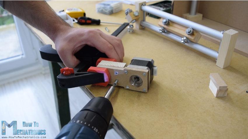
在另一个右侧的轨道,我不得不附加步进电机水平运动。首先,我把电机固定在一块8毫米的中密度纤维板上,然后在上面加了一块支撑木,还把开槽的部分固定在上面。最后,我用木胶和两个螺丝将整个组件连接到垂直滑块上。
接下来,我继续在水平滑块上添加容器。为此,我用了一些小木片,用木胶把它们连接起来。一旦我完成了这项工作,我就准备组装铁路系统。我用了一些环氧树脂在轨道槽,并添加了一个额外的木板,以使整个轨道系统更硬。
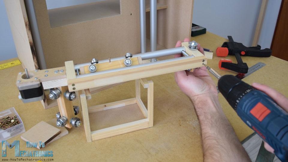
在下一步中,我将组件插入垂直轨道之间,并将其固定到位。滑块和导轨系统的最终结果是工作良好。
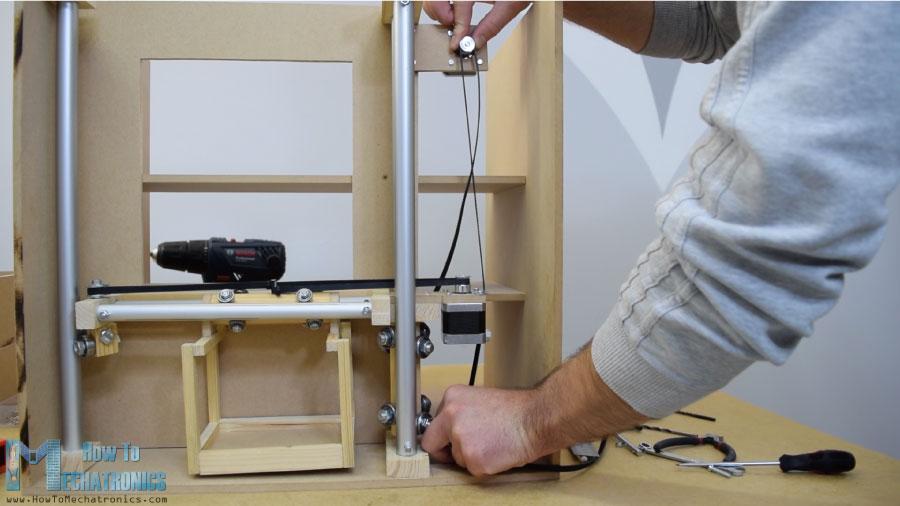
我继续安装水平同步带。我测量了我需要的长度,剪成一定的尺寸,然后用一个拉链把它固定在滑块上。至于垂直滑块,我用一块中密度纤维板和一些螺栓将步进电机安装在机器顶部。在底部,我连接了滑轮,并以类似的方式安装了正时皮带。
卸料装置
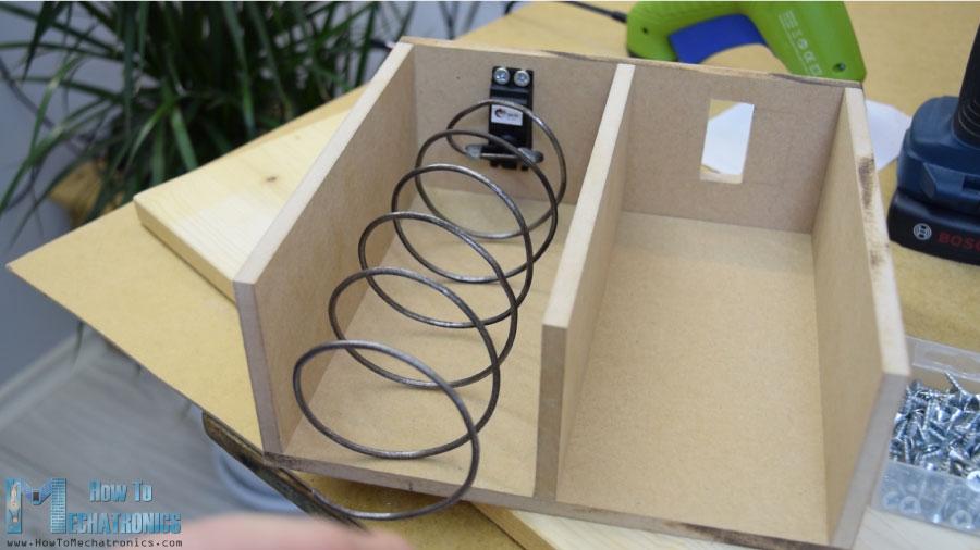
接下来,我转到卸料单元。我用3毫米厚的金属丝做了一个螺旋线圈,把它包裹在一个直径7厘米的喷漆罐上。
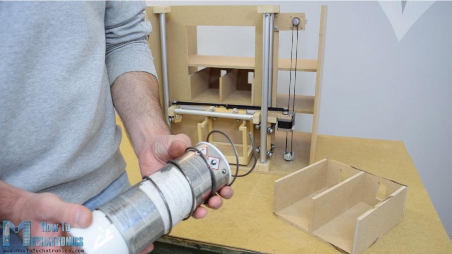
之后我用胶水枪把它固定在一个连续旋转的伺服电机上。
前面板
下一个是前门面板,我用简单的铰链连接到自动售货机上,为了锁上它,我用了一个磁性的门闩。然后我用一个5毫米厚的丙烯酸树脂覆盖前面的大开口,而对于右侧较小的开口,我用了一块非常锡的铝板。我在这里为硬币和纽扣做了4个洞. 我用钻头和钢锯做的。一旦我把电子部件连接到铝板上,我就用5毫米的螺栓将其固定到前门板上。
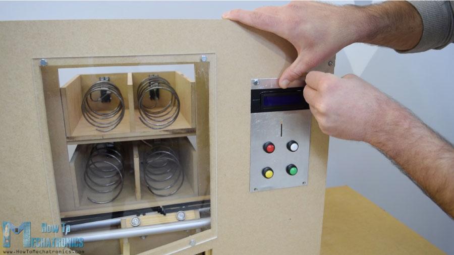
为了把载体定位到它的起始位置,我安装了两个微型开关,对于硬币,我粘了一个引导器,引导硬币滑到机器底部。
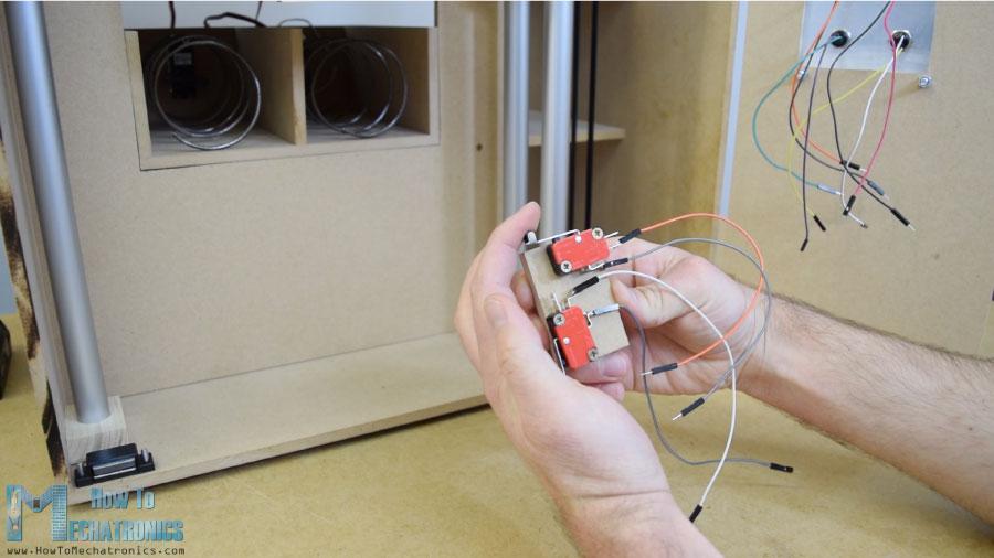
当硬币附近有一个简单的红外传感器时,它会给我们一个正面的反馈。
电路图
接下来是有趣的部分,将所有电子元件连接到Arduino板上。这是这个DIY自动售货机项目的完整电路图。
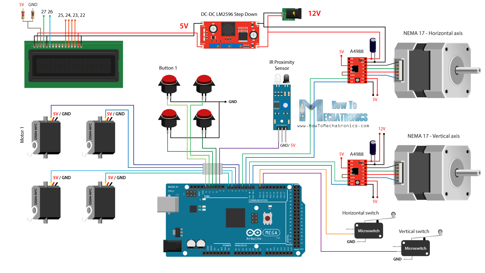
所以我们需要12伏电源,至少2安培。我们需要12伏的两个步进电机,以及LED灯条,我将稍后附加在前门。然而,对于所有其他组件,我们需要5V,因此我使用了一个降压转换器将12V降压到5V。DS04-NFC连续旋转伺服电机由5V供电,并通过来自Arduino板的PWM信号控制,而. 四个按钮和两个微动开关连接到接地和Arduino数字引脚,因此使用Arduino板的内部上拉电阻器,我们可以很容易地检测到何时按下它们。
您可以从以下链接获取本Arduino教程所需的组件:
DC-DC LM2596降压转换器
16×2液晶显示器
360度连续旋转伺服电机
步进电机NEMA 17
A4988步进电机驱动器
红外接近传感器
按钮
微型限位开关
Arduino板
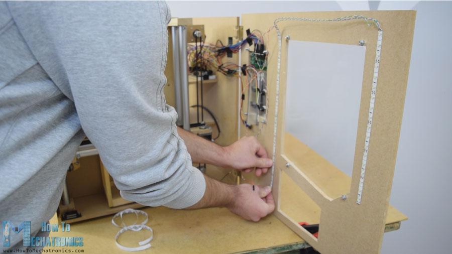
我用一些电子元件连接跨接线。它变得有点凌乱,有那么多电线,但一切正常。最后,我把两个LED灯条贴在门板上,照亮自动售货机的内部。
Arduino代码
现在剩下的就是编程Arduino,这是我为这个项目制作的代码。下面是代码的说明。
/* DIY Vending Machine - Arduino based Mechatronics Project
by Dejan Nedelkovski, www.HowToMechatronics.com
*/
#include <LiquidCrystal.h> // includes the LiquidCrystal Library
#include <Servo.h>
LiquidCrystallcd(27, 26, 25, 24, 23, 22);// Creates an LC object. Parameters: (rs, enable, d4, d5, d6, d7)
Servo servo1, servo2, servo3, servo4;// DS04-NFC motors
// Stepper motors pins
#define dirPinVertical 0
#define stepPinVertical 1
#define dirPinHorizontal 2
#define stepPinHorizontal 3
#define coinDetector 9
#define button1 13
#define button2 12
#define button3 11
#define button4 10
#define microSwitchV 15
#define microSwitchH 14
intbuttonPressed;
voidsetup(){
lcd.begin(16, 2);// Initializes the interface to the LCD screen, and specifies the dimensions (width and height) of the display
servo1.attach(4);
servo2.attach(5);
servo3.attach(6);
servo4.attach(7);
pinMode(dirPinVertical, OUTPUT);
pinMode(stepPinVertical, OUTPUT);
pinMode(dirPinHorizontal, OUTPUT);
pinMode(stepPinHorizontal, OUTPUT);
pinMode(coinDetector, INPUT);
// Activating the digital pins pull up resistors
pinMode(button1, INPUT_PULLUP);
pinMode(button2, INPUT_PULLUP);
pinMode(button3, INPUT_PULLUP);
pinMode(button4, INPUT_PULLUP);
pinMode(microSwitchV, INPUT_PULLUP);
pinMode(microSwitchH, INPUT_PULLUP);
// Vertical starting position
digitalWrite(dirPinVertical, HIGH);// Set the stepper to move in a particular direction
while(true){
if(digitalRead(microSwitchV)== LOW){// If the micro switch is pressed, move the platfor a little bit up and exit the while loop
moveUp(70);
break;
}
// Move the carrier up until the micro switch is pressed
digitalWrite(stepPinVertical, HIGH);
delayMicroseconds(300);
digitalWrite(stepPinVertical, LOW);
delayMicroseconds(300);
}
// Horizontal starting position
digitalWrite(dirPinHorizontal, LOW);
while(true){
if(digitalRead(microSwitchH)== LOW){
moveLeft(350);
break;
}
digitalWrite(stepPinHorizontal, HIGH);
delayMicroseconds(300);
digitalWrite(stepPinHorizontal, LOW);
delayMicroseconds(300);
}
}
voidloop(){
// Print "Insert a coin!" on the LCD
lcd.clear();
lcd.setCursor(0, 0);
lcd.print("Insert a coin!");
// Wait until a coin is detected
while(true){
if(digitalRead(coinDetector)== LOW){// If a coin is detected, exit the from the while loop
break;
}
}
delay(10);
lcd.clear();
lcd.setCursor(0, 0);
lcd.print("Select your item");
lcd.setCursor(0, 1);
lcd.print(" 1, 2, 3 or 4?");
// Wait until a button is pressed
while(true){
if(digitalRead(button1)== LOW){
buttonPressed = 1;
break;
}
if(digitalRead(button2)== LOW){
buttonPressed = 2;
break;
}
if(digitalRead(button3)== LOW){
buttonPressed = 3;
break;
}
if(digitalRead(button4)== LOW){
buttonPressed = 4;
break;
}
}
// Print "Delivering..."
lcd.clear();
lcd.setCursor(0, 0);
lcd.print("Delivering...");
// Depending on the pressed button, move the carrier to that position and discharge the selected item
switch(buttonPressed){
case1:
// Move the container to location 1
moveUp(4900);// Move up 4900 steps (Note: the stepper motor is set in Quarter set resolution)
delay(200);
moveLeft(1700);// Move left 1700 steps
delay(300);
// Rotate the helical coil, discharge the selected item
servo1.writeMicroseconds(2000);// rotate
delay(950);
servo1.writeMicroseconds(1500);// stop
delay(500);
// Move the container back to starting position
moveRight(1700);
delay(200);
moveDown(4900);
break;
case2:
// Move the container to location 2
moveUp(4900);
delay(200);
// Rotate the helix, push the selected item
servo2.writeMicroseconds(2000);// rotate
delay(950);
servo2.writeMicroseconds(1500);// stop
delay(500);
moveDown(4900);
break;
case3:
// Move the container to location 3
moveUp(2200);
delay(200);
moveLeft(1700);
delay(300);
// Rotate the helix, push the selected item
servo3.writeMicroseconds(2000);// rotate
delay(950);
servo3.writeMicroseconds(1500);// stop
delay(500);
// Move the container back to starting position
moveRight(1700);
delay(200);
moveDown(2200);
break;
case4:
// Move the container to location 4
moveUp(2200);// Move verticaly 4800 steps
delay(200);
// Rotate the helix, push the selected item
servo4.writeMicroseconds(2000);// rotate
delay(950);
servo4.writeMicroseconds(1500);// stop
delay(500);
moveDown(2200);
break;
}
lcd.clear();// Clears the display
lcd.setCursor(0, 0);
lcd.print("Item delivered!");// Prints on the LCD
delay(2000);
}
// == Custom functions ==
voidmoveUp(intsteps){
digitalWrite(dirPinVertical, LOW);
for(intx = 0; x<steps; x++){
digitalWrite(stepPinVertical, HIGH);
delayMicroseconds(300);
digitalWrite(stepPinVertical, LOW);
delayMicroseconds(300);
}
}
voidmoveDown(intsteps){
digitalWrite(dirPinVertical, HIGH);
for(intx = 0; x<steps; x++){
digitalWrite(stepPinVertical, HIGH);
delayMicroseconds(300);
digitalWrite(stepPinVertical, LOW);
delayMicroseconds(300);
}
}
voidmoveLeft(intsteps){
digitalWrite(dirPinHorizontal, HIGH);
for(intx = 0; x<steps; x++){
digitalWrite(stepPinHorizontal, HIGH);
delayMicroseconds(300);
digitalWrite(stepPinHorizontal, LOW);
delayMicroseconds(300);
}
}
voidmoveRight(intsteps){
digitalWrite(dirPinHorizontal, LOW);
for(intx = 0; x<steps; x++){
digitalWrite(stepPinHorizontal, HIGH);
delayMicroseconds(300);
digitalWrite(stepPinHorizontal, LOW);
delayMicroseconds(300);
}
}
源代码说明
首先,我们需要包括伺服和液晶库,定义LCD引脚、四个伺服电机、步进电机引脚、硬币探测器以及四个按钮和两个微型开关。
在设置部分,我们为上面提到的每个引脚设置引脚模式。我们可以注意到,对于按钮和微型开关引脚,我们激活了内部上拉电阻器。这意味着这些引脚的逻辑电平将一直处于高位,一旦我们按下它们,逻辑电平将下降到低位。
在我们进入主回路之前,我们还将载波设置到由两个微动开关定义的起始位置。因此,在while循环中,我们继续将载体移动到其起始位置,一旦按下两个微动开关,电机将停止并移动到所需的启动位置。
// Vertical starting position
digitalWrite(dirPinVertical, HIGH);// Set the stepper to move in a particular direction
while(true){
if(digitalRead(microSwitchV)== LOW){// If the micro switch is pressed, move the platfor a little bit up and exit the while loop
moveUp(70);
break;
}
// Move the carrier up until the micro switch is pressed
digitalWrite(stepPinVertical, HIGH);
delayMicroseconds(300);
digitalWrite(stepPinVertical, LOW);
delayMicroseconds(300);
}
// Horizontal starting position
digitalWrite(dirPinHorizontal, LOW);
while(true){
if(digitalRead(microSwitchH)== LOW){
moveLeft(350);
break;
}
digitalWrite(stepPinHorizontal, HIGH);
delayMicroseconds(300);
digitalWrite(stepPinHorizontal, LOW);
delayMicroseconds(300);
}
在主程序中,首先在LCD上打印"插入硬币"消息。然后我们被困在while循环中。一旦插入一个硬币,它通过接近传感器,硬币探测器引脚的逻辑状态将下降到低,在这种情况下,我们将使用break语句退出while循环。
// Wait until a coin is detected
while(true){
if(digitalRead(coinDetector)== LOW){// If a coin is detected, exit the from the while loop
break;
}
}
我们在循环中选择另一条信息然后打印。
// Wait until a button is pressed
while(true){
if(digitalRead(button1)== LOW){
buttonPressed = 1;
break;
}
if(digitalRead(button2)== LOW){
buttonPressed = 2;
break;
}
if(digitalRead(button3)== LOW){
buttonPressed = 3;
break;
}
if(digitalRead(button4)== LOW){
buttonPressed = 4;
break;
}
}
这个while循环等待我们按下四个按钮中的任何一个,一旦我们按下了,我们就会退出并打印消息"Delivering"。
现在,根据按下的按钮,我们在switch语句中执行一次case。如果我们按下了第一个按钮,运营商将开始使用定制的"moveUp()"函数上移。
switch(buttonPressed){
case1:
// Move the container to location 1
moveUp(4900);// Move up 4900 steps (Note: the stepper motor is set in Quarter set resolution)
delay(200);
moveLeft(1700);// Move left 1700 steps
delay(300);
// Rotate the helical coil, discharge the selected item
servo1.writeMicroseconds(2000);// rotate
delay(950);
servo1.writeMicroseconds(1500);// stop
delay(500);
// Move the container back to starting position
moveRight(1700);
delay(200);
moveDown(4900);
break;
}
如果我们看一下这个函数,我们可以看到它只是将步进电机设置为向特定的方向移动,并使我们输入的步数作为参数。
voidmoveUp(intsteps){
digitalWrite(dirPinVertical, LOW);
for(intx = 0; x<steps; x++){
digitalWrite(stepPinVertical, HIGH);
delayMicroseconds(300);
digitalWrite(stepPinVertical, LOW);
delayMicroseconds(300);
}
}
我们可以注意到,我设置了A4988步进驱动器的工作在四分之一步的分辨率,和一些品味,我得出结论,我需要4900步,以使载体达到较高的位置。以类似的方式,我们将载体向左移动,直到到达位置1。
紧接着,我们旋转连续旋转电机950毫秒,使螺旋线圈完成一个完整的循环。
// Rotate the helical coil, discharge the selected item
servo1.writeMicroseconds(2000);// rotate
delay(950);
servo1.writeMicroseconds(1500);// stop
请注意,这些值有时会变化,并取决于电机本身。使用moveRight()和moveDown()自定义函数,我们将载体带回起始位置。以同样的方式,我们可以卸下这四个项目中的任何一个。
最后我们只打印消息"项目已送达"。
*博客内容为网友个人发布,仅代表博主个人观点,如有侵权请联系工作人员删除。