
一种测试系统数字稳压电源的设计方案

图3 PID控制算法流程图。
PID控制算法程序采用结构体定义:
struct PID{
unsigned int SetPoint; //设定目标Desired Value
unsigned int Proportion; //比例常数Proportional Const
unsigned int Integral; //积分常数Integral Const
unsigned int Derivative; //微分常数Derivative Const
unsigned int LastError; //Error[-1]
unsigned int PrevError; //Error[-2]
unsigned int SumError; //Sums of Errors
}spid;
在PID控制算法中,经过不断与给定值进行比较,动态控制电压电流输出的稳定,同时确保电压电流输出的精度。
PID控制算法程序如下:
unsigned int PIDCalc(struct PID *pp,unsigned int Next-Point)
{
unsigned int dError,Error;
Error=pp->SetPoint-NextPoint; //偏差
pp->SumError+= Error; //积分
dError=pp->LastError-pp->PrevError; //当前微分
pp->PrevError=pp->LastError;
pp->LastError= Error;
return(pp->Proportion* Error //比例
+pp->Integral*pp->SumError //积分项
+pp->Derivative*dError); //微分项
}
3.4 系统程序
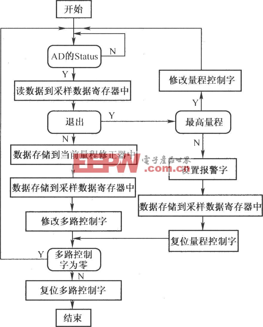
测试系统的整体程序流程图如图4所示。
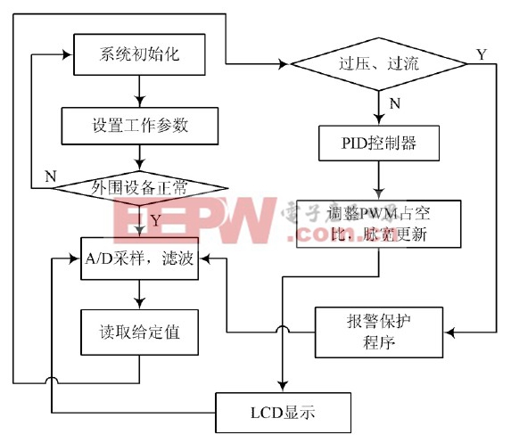
图4 主程序流程图
本文所设计的测试系统数字稳压电源能够满足芯片测试所需的电源要求。图5为输出的一路电压。由图可知,所输出的电压稳定。
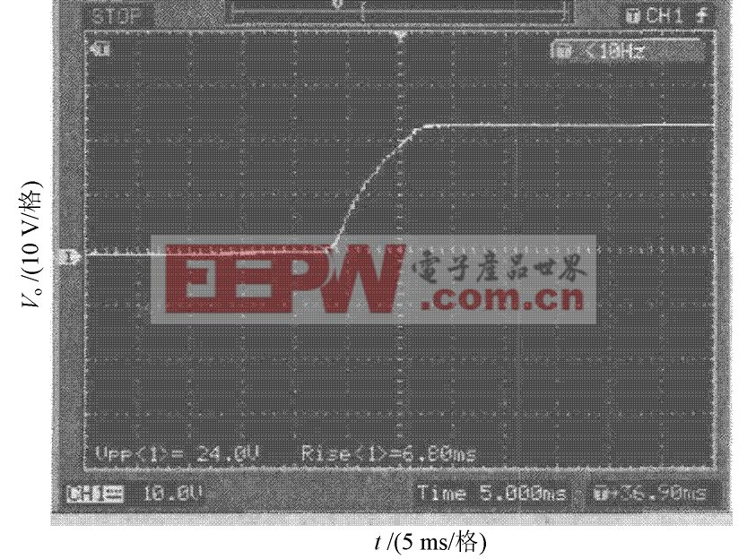
图5 输出电压波形图
4 结 语
本文设计的稳压电源提供的电压稳定可靠,系统运行也非常稳定。由于可扩展的I/O 非常多,可以同时为多个芯片提供各种所需的稳压电源电压值。该系统不仅能够用在实验室芯片测试工作中,而且可以通过软件编程的方法,修改一些控制程序,使所设计的稳压电源作为智能电子产品性能测试的电源电压,这样提高了设备的使用效率,有着不错的应用前景。


评论